
A Second Saturn Launch Complex-LC-37
Block I - the first four Saturn launches had gone up from launch complex 34. With the block II launches (SA-5 through SA-10), the program would move to new facilities at launch complex 37. The second complex had originated with the Hall Committee study of 1959, which found that an explosion would render LC-34 useless for a year [chapter 2-6]. On 29 January 1960 Debus asked Dr. Eberhard Rees to approve a second Saturn complex. Since LC-37 would serve primarily as insurance for LC-34, no major design changes were anticipated. Taking into account the rising costs on complex 34, Debus estimated the price of LC-37 at $20 million (roughly one-third more than LC-34's costs as of January 1960). In his report, Debus warned Rees that LC-37 would likely be sited at the undeveloped north end of Cape Canaveral, 1,220 meters north of LC-34 and 425 meters from the Atlantic Ocean. A complex at that location "would require utility capacities of unusually large magnitudes and the cost to Saturn, as the initial [user] could be excessive."9 In February 1960, representatives from the Missile Firing Laboratory, Army Ballistic Missile Agency, and the Air Force Missile Test Center estimated demands for water, power, roads, communications, and instrumentation at LC-37 and discussed the cost of extending these to the proposed site. Eventually, development for LC-37 included a new electrical power substation and transmission lines, a 3,785,000-liter water reservoir, and a pumping network, at a price of $2.5 million.10
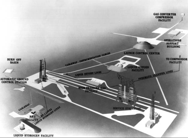
Proposed launch complex 37.
Hoping to have LC-37 ready for backup duty by January 1962, MFL originally set a mid-1960 deadline for criteria on the launcher, umbilical tower, and propellant systems.11 Debus's decision to put a new service structure on LC-37 dashed these plans. Harvey Pierce, a Connell engineer, had prompted the change. Pierce had played an important role in designing LC-34 and more recently on the Hall Committee. On 26 February Pierce had written Debus about some inherent shortcomings in the inverted U service structure and recommended the formation of a study group.12
By mid-April 1960 Albert Zeiler was directing a two-pronged investigation into problems encountered with LC-34's service structure and concepts for a larger one. The latter reflected NASA's decision to build LC-37 for both C-1 and C-2 versions of the Saturn.13 The service structure committee met periodically over three months to review 21 concepts proposed by NASA officials and private industry. No proposal proved fully satisfactory; attractive features from several were combined in the final recommendation. The committee concentrated on a half-dozen aspects of the service structure design, posing these alternatives:
- Mobile or fixed structure?
- Bridge crane or stiff-leg derrick for hoisting?
- Protection for the launch vehicle from wind loading or absorption of the rocket's wind loads into the service structure?
- Open or closed service platforms?
- Launch stand above or below ground?
- Collapsible or fixed umbilical tower?
The hoisting matter was settled in favor of a stiff-leg derrick mounted on top of the service structure. Although a bridge crane offered more flexibility, its use in the upper reaches of the service structure would obstruct the vertical escape trajectory of a manned payload. In the final design a 40-ton mobile crane positioned at a lower level assisted the 60-ton main hook on the stiff-leg derrick.
The question of wind loads arose because the Saturn was not self-supporting in high winds. One alternative was to design "hard point" connections between the vehicle and service structure platforms. This would require additional structural members on the rocket, increasing its empty weight. It would also add considerable stress to the service platform. The committee chose a design enclosing the launch vehicle in a 76-meter silo of five sections that eliminated wind loads and protected the rocket from flying debris. The silo design also solved the service platform problem. The committee recommended a minimum of ten adjustable work platforms in the structural steel frame silo. Air conditioning would provide the necessary ventilation during propellant loading.
The committee rejected a plan to put the launch stand below ground with the flame diverted into side trenches. Doing so would reduce the height of the service structure, but the higher costs of subsurface facilities, due to Cape Canaveral's high water table, were unacceptable.15
In designing the umbilical tower, the major concern was separation of the umbilical connections from the launch vehicle at liftoff. The committee studied jointed, collapsing towers; towers supported by cable catenaries (a curved cable suspended from two poles); and pivotal reclining structures. The size and weight of the Saturn umbilical connections - propellant piping, pneumatic lines, instrumentation circuitry, and electrical power lines - rendered all those concepts impractical. The committee recommended a free-standing umbilical tower, with ties to the service structure for support against high winds. Swing arms, entering the silo enclosure through cutouts in the platform mating edge, would connect the umbilicals to the launch vehicle.16
In August 1960 the launch team approached von Braun about adding a second pad to the LC-37 complex. The additional pad would provide a backup for Saturn C-2 launches and reduce launch time by one-third, since it would eliminate the month needed for pad repairs. Von Braun directed Debus to add a second pad on LC-37 if funds could be secured. Before the meeting adjourned, General Ostrander, Office of Launch Vehicle Program Director, arrived. After reviewing the proposal, Ostrander agreed to provide $700,000 for the initial modification work.17
Further revision of LC-37 plans occurred in early 1961. In January Debus heard of an Air Force-sponsored study on blast potentials of the Atlas-Centaur rocket. The Arthur D. Little Company findings, Debus informed von Braun, "indicated a problem of considerable magnitude with Saturn complex siting."18 Since there was little data on liquid hydrogen's explosive characteristics, the calculations were tentative. The Little report, however, reinforced the Hall Committee's conclusions. On 12 January Debus asked Petrone, as Saturn project coordinator, to investigate the explosive potential of liquid hydrogen and determine the cost of extending pad distances beyond 183 meters. The distance between pads was subsequently increased to 365 meters.19
Two Florida firms won the LC-37 design contract: Connell and Associates prepared the service structure and umbilical tower designs, while Reynolds, Smith, and Hills handled the subsurface facilities. The architects' design work extended from February to July 1961. During the same period, Gahagan Company dredged thousands of cubic meters of sand from the Banana River onto the LC-37 site. Vibroflot machines began their work at the complex in mid-July. Blount Brothers Construction Company of Montgomery, Alabama, won the pad B construction bid in August 1961 and started work the following month. The project was 45% complete on 30 March 1962, when the Corps of Engineers awarded Blount Brothers a contract to build pad A.20
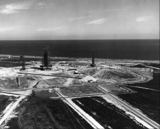
LC-37 under construction, January 1963.
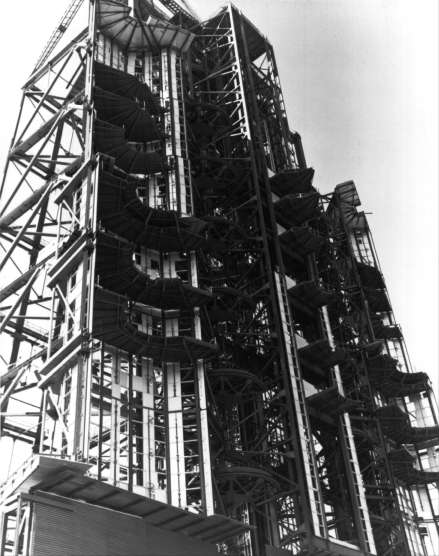
The new construction soon overshadowed the older Saturn facility. LC-37 was nearly three times larger than LC-34. The two umbilical towers rose 82 meters from a 10-meter-square base. Stability of the towers in high wind presented a challenge to the designers. The large number of electrical, propellant, and pneumatic lines running up through the lofty structures gave the tower surface a wind resistance nearly equivalent to a solid wall. At the base of each tower stood a four-story building (one floor was underground) containing a generator room, high-pressure-gas distribution equipment, and a cable distribution center. The building would later house digital computers for the automated checkout.21 Hydrogen burn ponds were an added feature on LC-37. The gaseous hydrogen boiled off from the LH2 storage tank and the S-IV stage and flowed several hundred meters through pipes to the burn pond. The LC-37 launch control center, or blockhouse, was similar to LC-34's, but half again as large. By far the most imposing of LC-37's facilities was a 4,700-ton, 92-meter-high service structure, containing four elevators, nine fixed platforms, and ten adjustable platforms that allowed access to all sides of the vehicle. The six semicircular enclosures could withstand 200-kilometer-per-hour winds. When completed in 1963, the self-propelled, rail-mounted structure was the largest wheeled vehicle in the world.22
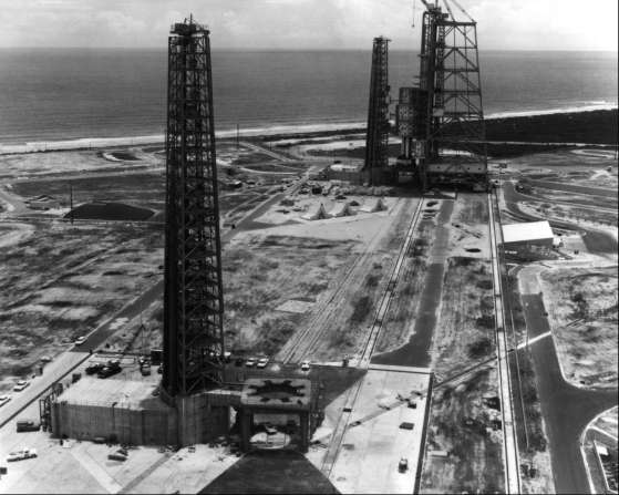
The LC-37 service structure at pad B.
The LC-37 service structure in the open position, February 1963.
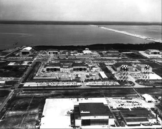
The industrial area on the Cape. Hanger AF is in the upper left. The causeway (under construction) leads to Merritt Island in the distance.
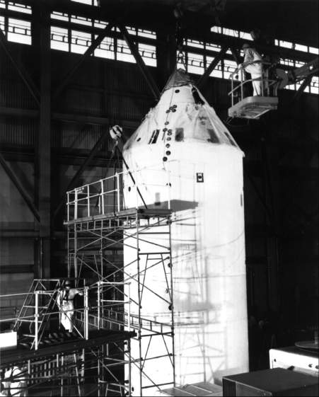
Mating spacecraft modules inside Hanger AF, March 1964
Erection of a special assembly building was a third construction project for Saturn I in 1962. Some novel building designs were rejected before deciding on a conventional hangar configuration. The new hangar AF was in the Cape industrial area, a short distance from the Saturn dock. A bridge crane in the hangar's main bay provided a lift capability for the initial upper stage checkout; lean-tos on both sides provided extra office space. The Launch Vehicle Operations Division performed some preliminary checkout work in hangar AF, but half of its big bay was soon given over to Gemini and Apollo spacecraft operations.23
| Next |