
Flame Deflector and Launch Pads
If any one item virtually dictated the design of the launch pad, it was the flame deflector. This device would send the fiery exhaust of the five firststage engines along the flame trench. The LOC designers who established criteria for the pads had wanted to keep the Saturn vehicle as close to the ground as possible in order to lessen wind stresses. They settled on a two-way, wedge-type flame deflector similar in design to those used on pads 34 and 37. The deflector, 13 meters in height and 15 meters in width, would weigh 317 tons. Since the water table was close to the surface of the ground, the criteria group wanted the bottom of the flame trench at ground level. The flame deflector and trench determined the height and width of the octagonal shaped launch pad; this in turn set the width of the space between the crawler treads, because the crawler straddled the pad.
Sketch of LC-39 pad, with enlargement of the flame deflector, May 1963.
During the last week of June and throughout July and August 1962, tests on 1:58 scale-model flame deflectors were conducted by the Test Division and Aeroballistics Division at Huntsville. They found that the launch complex 37 deflector, a copper, water-cooled, ridged model, suffered serious erosion from the concentration of heat and high gas velocities. By March 1964, the preliminary designs for a steel deflector and for a reinforced concrete deflector had been completed. By means of instrument readings and motion pictures, the aerothermodynamic flow characteristics were determined, and the flame deflector and trench designs were refined. In designing the deflectors for launch complex 39 pads, it was necessary to have a replaceable leading edge which eroded but was insulated. Four types of deflector ridges were tested, using information gained in the study of heat-resistant shapes and materials for the Jupiter-C nose cone. When sufficient evidence was gathered, the design of the deflector proceeded with dispatch.34
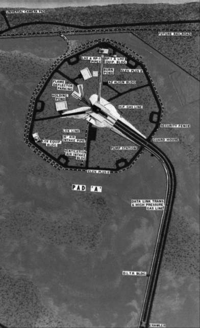
Model of pad A, LC-39, February 1963.
The design of launch pads A and B presented further difficulties, many of which concerned the slab that covered the pads. This hardstand had to support the crawler-transporter and its pressure of 50 tons per square meter. Under a new proposal, a cellular construction, something like orange crates set in two rows, would support and protect the area adjacent to the flame deflector trench and beneath the crawler. The cellular construction, extending the full length of the flame deflector pit on either side, would provide an explosion buffer to the main launch facilities, reduce the pressure on the launch pad foundations, and offer additional space for service items.35
The selection of a refractory surface for the walls, floor, and an area outside of the flame trench was exacting. Such a surface had to withstand temperatures of 1,922 kelvins and flame velocities four times the speed of sound. Special refractory fire bricks were held to the walls by interlocks, mechanical anchors, and a modified epoxy cement. All concrete surfaces protected by the brick had to have a smoothness tolerance of 0.3 centimeters in 3 meters to provide a bonding surface. This careful work was to limit the maximum temperature in the adjacent concrete structure during launch to 310 kelvins (37 degrees C).36
Other components of the launch pad that required detailed design studies included the terminal connection room, the environmental control system, the high-pressure-gas storage facility, and the emergency egress system. The connection room, which contained extensive instrumentation facilities for testing during prelaunch and launch phases, and the environmental control system, which maintained the temperatures of the vehicle and compartments prior to launch, were designed to withstand concentrated pressures at any point. These rooms would protect ground support equipment located at the launch pad from heat, vibration, and shock during launch.37
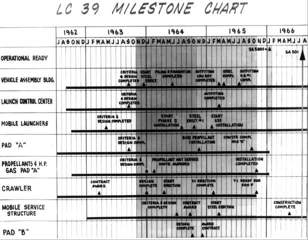
LC-39 milestone chart, December 1964.
By 1 June 1962, the design concept for the Saturn V propellant loading, high-pressure gases, and associated systems had been established. To use a reliable automated system and eliminate the cost of developing a new one, a modified version of the automatic propellant loading and associated systems used for LC-37 was selected for LC-39. Propellant servicing was controlled from the launch control center. Most of the hardware for the propellant-loading system was located in the terminal connection room at the pad. This room contained separate areas for each propellant and its associated systems. The remote command and display equipment in the control center was connected by an independent digital data transmission link to the hardware at the pad, which in turn was connected to the transporter-launcher and the storage facilities by electrical lines. Consequently, control commands could be initiated from the transporter-launcher, the launch control center, or the terminal connection room at the pad during servicing and checkout.38
| Next |