
Launch Pads
The launch pads at complex 39 were more than just raised, hardened areas for the launching of the Saturn V. There would be no permanently emplaced launch stands, umbilical towers, and service structures as previously associated with a complete launch complex. At LC-39 these structures would be mobile, and the pad had to be of sufficient strength to support their weight and that of the crawler-transporter. But the pad would have many other appurtenances common to its predecessors.
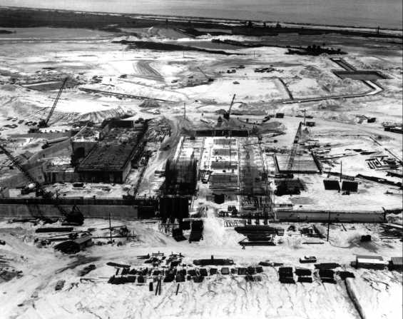
Construction of pad A, LC-39. (1) Looking North, July 1964. The large sandpile has been removed and the first concrete poured. The rectangle (upper right) is the hydrogen burn pond.
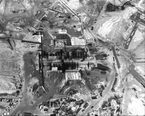
Construction of pad A, LC-39. (2) The cellular construction of the hardstand, either side of the flame trench, is evident by September. The view is to the west.
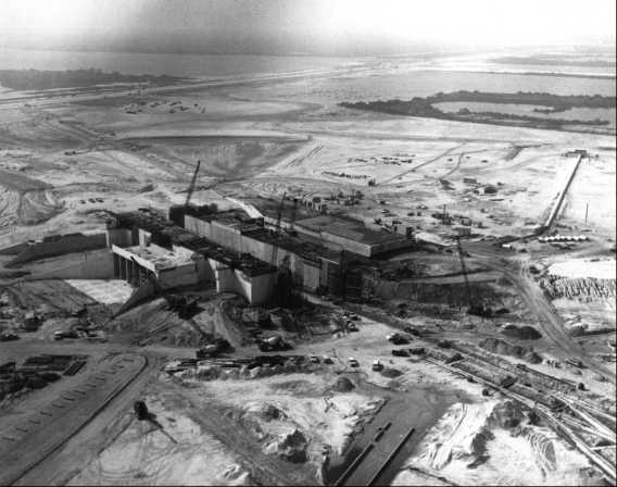
Construction of pad A, LC-39. (3) Looking southwest, November. Most of the concrete has been poured.
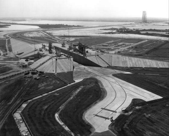
Construction of pad A, LC-39. (4) Same view two months later; pad 39A essentially complete. The flame deflector would move along the tracks in the foreground. The crawlerway enters the picture in the upper right, passes the service structure (née arming tower) in its parking position, and makes a near-90 degree turn in the upper left to approach the pad.
The site of launch pad A, approximately 0.7 square kilometers, was roughly octagonal. A contract with Blount-Sundt called for the construction of the pad proper, roads, camera mounts, utilities, and several other small facilities. The elevated launch pad, which would rise 12 meters above ground level, lay in a north-south direction. This orientation required the crawlerway to make a near right-angle turn before approaching the ramp sloping 5 degrees upward to the top of the pad. A flame trench, level with the surrounding area at its base, 18 meters wide and 137 meters long, would bisect the pad. On each side of this flame trench a cellular structure would support a thick surface, called a hardstand. The crawler-transporter would place the mobile launcher and the Apollo-Saturn vehicle on top of this reinforced slab.
The two-story pad terminal connection room and the single-story environmental control systems room would be within the western side of the pad. The former would house the electronic equipment that would connect communication and digital data link transmission lines from the launch control center to the mobile launcher when it was on the pad. The environmental control systems room would serve as the distribution point for air conditioning and water systems. The high-pressure-gas storage facility, to store and distribute nitrogen and helium gases piped from the converter-compressor facility, would lie beneath the top of the pad on the east side.
Should a hazardous condition arise that allowed safe egress from the spacecraft, the astronauts could cross over to the mobile launcher on a swing arm and then ride one of the high-speed elevators from the 104- meter level to level A, thirty stories down at 183 meters per minute. From there they would slide down an escape tube to a thickly padded rubber deceleration ramp. Steel doors, much like those of a bank vault, allowed access to a blast room, which could withstand an on-the-pad explosion of the entire space vehicle. Those inside could stay alive for at least 24 hours to allow rescue crews time to dig them out. The emergency egress system was part of the pad A contract.40
| Next |